
§2013-10-14(国际核聚变严重歧视中国 投资10亿欧元仅让打杂)
§2013-10-07(Nuclear fusion milestone passed at US lab)Researchers at a US lab have passed a crucial milestone on the way to their ultimate goal of achieving self-sustaining nuclear fusion.
■NIF
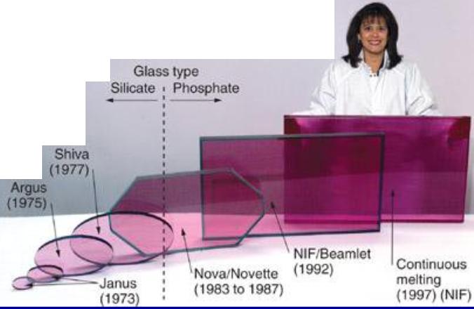
美国国家点火装置(NIF),由位于美国加利福尼亚州劳伦斯·利弗莫尔国家实验室研制。该计划自1994年开工以来延期了很多次,它的目标是希望2010年实现聚变反应,并达到平衡点,即激光在聚变反应中产生的能量大于它们所消耗的能量。该计划建造和运行花费超过35亿美元,容纳NIF装置的建筑物长215米,宽120米,相当于三个足球场。
美国国家点火装置的实验过程为:先将外部激光增强10000倍,然后将一束激光分离为48束激光,再增强,进一步分离为192束激光,其总能量增加到原来能量的3000万亿倍,再聚焦到直径为3毫米的氘氚小丸上,产生1亿度的高温,压力超过1000亿个大气压,进而引发核聚变。每束激光发射出持续大约十亿分之三秒、蕴涵180万焦耳能量的脉冲紫外光——这些能量是美国所有电站产生的电能的500倍还多。当这些脉冲撞击到目标反应室上,它们将产生X光。这些X光会集中于位于反应室中心装满重氢燃料的一个塑料封壳上。X光将把燃料加热到一亿度,并施加足够的压力使重氢核生聚变反应。释放的能量将是输入能量的15倍还多。这是因为激光在镜面之间来回反射,并通过3000块磷酸盐玻璃,其中的钛原子会使激光束扩大。利弗莫尔有850名科学家和工程师。另外大约有100名物理学家在那里设计实验。NIF的问题是它的激光每几小时只能发射一次。
■Mercury激光装置走向实际激光聚变
《Laser Focus World》2009年3月发表美国劳伦斯·利弗莫尔国家实验室(Lawrence Livermore National Laboratory, LLNL)Chris Ebbers等人的文章,介绍高功率固体激光装置——Mercury激光装置以及进展。Mercury激光装置由二极管泵浦,脉冲能量100J,重复频率为10Hz。Mercury激光装置研制将推进高重复率惯性激光聚变不断向前发展。
建造在美国劳伦斯·利弗莫尔国家实验室的国家点火装置(National Ignition Facility, NIF)将验证“得失相当”,也就是产生的聚变能输出等于输入的激光能量。国家点火装置将输出光束压缩氢同位素构成的球形靶丸,使其发生聚变,释放大量能量。得失相当的获得凝聚了过去几十年来全世界众多科学家和工程人员的努力。
但是获得得失相当以后该做什么呢?国家点火装置适合工程研究,而激光聚变则要产生电能供人使用。而要实现这一目的,激光器必须有较高的频率,每秒大约要发射十发,而国家点火装置一天才能打几次靶,激光器的频率需要提高100000倍才能达到要求。Mercury激光装置的研制目的就是发展每秒十发、电激发的驱动激光器,用于商业激光聚变。Mercury激光装置输出脉冲的峰值功率仅为国家点火装置的1/30000,但具有更高的平均功率。
Mercury激光装置与国家点火装置之间存在着许多不同之处,其中之一是国家点火装置利用氙灯泵浦,而Mercury激光装置由高效率的激光二极管泵浦。Mercury激光装置是一个原型装置,口径和能量与国家点火装置一路束线参数按比例缩小,既具有更高的电效率,同时又能够以高重复率运行的大型装置。国家点火装置的目标是获得聚变得失相当,Mercury激光装置的主要目的是验证二极管抽运的固体激光器成为惯性聚变能电厂驱动装置的可行性。二极管泵浦减小了热量在Mercury激光装置中的沉积,而气体冷却也将剩余的热量有效地去除。
系统设计
Mercury激光系统是高平均功率激光器项目重点研究的两种聚变驱动装置之一。Mercury激光系统采用角多路传输结构,如图1所示,包括一个前端激光器和两个气体冷却放大器。放大器利用高速氦气冷却,减小放大器的光学畸变,确保10Hz的高重复能力;每个放大器包括4组峰值功率为100kW的二极管阵列,从两侧抽运气体冷却放大器头中7块Yb:S-FAP晶体片(4cm×6cm),确保Mercury激光系统的高能量效率;采用离轴四程放大结构,避免使用大口径高功率光开关;利用泡克耳斯盒抑制寄生振荡;两放大器间的中继成像(Relay Imaging)降低了放大介质因激光强度调制过大而损坏的危险,确保了放大器的可靠性。Mercury激光装置由光纤激光器提供种子脉冲,经前置放大器后,种子脉冲能量达到0.5J。预放大后的脉冲依次经过两个放大器,由反射镜反射回来后,再次经过两放大器获得最佳的能量输出。脉冲被放大至最大能量后,输入频率转换器。到今天为止,Mercury激光装置已经输出能量大于50J的发射已经超过300000次,重复频率保持在10Hz的水平。完全研制成功后,Mercury激光装置将保持相同的重复频率,输出能量达到100J脉冲。
增益介质
Mercury激光装置选用了Yb:S-FAP晶体作为其首选的增益材料,其选择原则主要考虑了晶体量子数亏损(quantum defect)、上能级寿命和发射截面等三方面的性能。晶体的这些性能决定着Mercury激光装置效率、成本和使用寿命等重要因素。Yb掺杂物吸收近900nm的二极管泵浦光而发射近1047nm的激光,表明Yb:S-FAP晶体的量子数亏损为15%,也就是说,15%的泵浦能量必须作为无用的热量去除掉。上能级的寿命长短很重要,它直接关系到为得到激光器输出一定能量所需的二极管激光泵浦能量数。为了实现100J的能量输出,Mercury激光装置必须泵浦至少115J使放大器的粒子数反转。Yb:S-FAP晶体的上能级寿命为1.1ms,意味著泵浦光的功率需要超过100kW。如果改用磷酸盐钕玻璃的话,其360 μs 的上能级寿命使得二极管的泵浦功率要超过300kW。另外,经过过去几十年的研究,Nd玻璃激光器相对要成熟多,而Yb:S-FAP晶体在很多方面与钕玻璃的性能相似。
自动控制
与国家点火装置相同,Mercury激光装置也采取远程校直和诊断。关键的光学元件一直处于监控中。如果高重复系统的一次发射过程发生光学损伤,不可能在下一发射引起进一步的破坏前人工关闭系统。因此,需要一套系统对发射数据进行收集和整理,并且能够在必要时安全关闭系统,并更换相应的光学元件,避免更多的光学元件被破坏。自动系统会对正在进行的激光发射与以前发射的数据相比较,任何比较大的不同都会被标记出来,并在下一发射前安全关闭系统。
原文:
Mar 1, 2009
The diode-pumped Mercury laser will deliver 100 J pulses at 10 Hz under automatic control, advancing the development of high-repetition-rate inertial laser fusion.
The National Ignition Facility (NIF) at Lawrence Livermore National Laboratory is on target to demonstrate “breakeven”–creating as much fusion-energy output as laser-energy input. The NIF laser will compress a tiny sphere of hydrogen isotopes with 1.8 MJ of light in a 20 ns pulse, packing the isotopes so tightly that they fuse together, producing helium nuclei and releasing energy in the form of energetic particles. The achievement of breakeven will culminate an enormous effort by thousands of scientists and engineers, not only at Livermore but around the world, during the past several decades.
But what about the day after NIF achieves breakeven? The National Ignition Facility is well suited for engineering research, but if laser fusion is ever to generate power for civilian consumption, the laser will have to deliver pulses nearly 100,000 times faster than NIF–a rate of perhaps 10 shots per second as opposed to NIF’s several shots a day.
The Mercury laser (named after the Roman messenger god) is intended to lead the way to a 10-shots-per-second, electrically efficient driver laser for commercial laser fusion. While the Mercury laser will generate only a small fraction (1/30,000) of the peak power of NIF, it operates at a higher average power. The design of Mercury takes full advantage of the technology advances manifest in its behemoth cousin (see table).
One significant difference is that, unlike the flashlamp-pumped NIF, Mercury is pumped by highly efficient laser diodes. Mercury is a prototype laser capable of scaling in aperture and energy to a NIF-like beamline with greater electrical efficiency, while still running at a repetition rate 100,000 times greater. While the goal of NIF is to achieve fusion breakeven, the goal of the Mercury laser system is the demonstration of a reliable diode-pumped solid-state laser system capable of scaling in aperture to the equivalent energy of a single one of NIF’s 192 beamlines. Diode pumping reduces the heat deposited into the Mercury laser, while gas cooling allows the residual heat to be efficiently removed.
Mercury is seeded by a precision fiber-based laser (see Fig. 1). This seed pulse is amplified in the preamplifier to an energy of 0.5 J and injected toward the first amplifier. The pulse passes through the first and second amplifiers and is reflected back through both, and then sent back for a third and fourth pass through the amplifiers to provide optimum energy extraction. After being amplified to its maximum energy, the pulse is directed toward the frequency converter. To date, Mercury has operated for more than 300,000 shots at greater than 50J at a repetition rate of 10 shots per second. Ultimately, Mercury’s goal is to generate 100 J pulses at this rate.
FIGURE 1. Light from the seed laser (not shown), which emits 0.5 J pulses, is injected by the optics toward the left into the diode-pumped, helium-gas-cooled Mercury laser amplifier. The beam is amplified after passing through each laser head twice. Angular multiplexing allows the beam to bypass the initial injection mirror and instead traverse through the box of four mirrors and the Pockels cell to be reinjected for a series of two more passes–a total of four, one-way gain passes through each amplifier. After the final pass, the beam travels to the frequency converter, where the IR light is converted to green light, the second harmonic.
The pumping geometry in Mercury is different from NIF’s (see Fig. 2). Using laser diodes to pump Mercury enables an order-of-magnitude increase in electrical efficiency compared to NIF. Each of Mercury’s two amplifiers is pumped by four 80kW laser-diode arrays. The diode light is first angularly redistributed by hollow concentrating optics to a 3 × 5 cm2 aperture in which the angular divergence of the beam is made nearly identical in both the x and y axes. The diode light is then guided by a rectangular reflective cavity, which maintains the angular distribution while smoothing the spatial profile.
The amplifiers are face-cooled with high-pressure helium gas, removing approximately 3 W/cm2 of heat with minimal thermal wavefront distortions. Helium is chosen for two unique properties: its low refractive index and its high thermal conductivity. One advantage of gas cooling is that the technology is scalable–once a system design has been formulated to remove a certain amount of heat per square centimeter, it is possible to scale in aperture, allowing a small-energy (100 J) laser system to operate with the same characteristics as a large-aperture system with 100 times more energy. This heat-removal method is applicable not only to the laser gain medium, but also to the frequency-conversion system, in which the IR laser emission is converted to green or UV light.
Comparison of the Mercury laser system to NIF
The design of a complex laser facility is driven by multiple, sometimes conflicting, issues. Here, we’ll concentrate on three issues involving the selection of gain material, because that selection has the most direct impact on efficiency, cost, and durability. These issues are: quantum defect, upper-lasing-level lifetime, and emission cross section. Essentially, these can be translated to the amount of energy (heat) left in the laser gain medium after efficient lasing, the number of diode pump lasers required to effectively provide the gain, and the amount of laser light (fluence) needed to circulate through the laser gain medium to efficiently extract the stored energy.
The quantum defect is important because it determines the amount of waste heat that must be removed from the gain medium. We selected crystalline strontium fluoro-apatite doped with ytterbium (Yb:S-FAP) as the gain medium for Mercury. The ytterbium dopant absorbs diode light near 900nm and emits near 1047 nm, indicating a quantum defect of 15%. In other words, an absolute minimum of 15% of the pump energy must be removed as waste heat.
FIGURE 2. The National Ignition Facility (top) is a flashlamp-pumped laser system, intended to fire up to six shots per day (0.0001 Hz). To increase the repetition rate by 100,000 (10 Hz), the Mercury laser system (bottom) must use active cooling. Diode lasers (as opposed to flashlamps) reduce the thermal loading on the laser gain medium. High-speed helium gas circulates across the amplifiers, allowing efficient removal of the residual heat.
The upper-state lifetime is important because it directly affects the number of diode-laser pumps required to achieve a given energy output from the laser. The longer the upper-state lifetime, the longer the diodes have to pump the necessary energy into the population inversion. To achieve a 100 J output with its 15% quantum efficiency, Mercury must pump at least 115 J into its amplifiers’ population inversions. Yb:S-FAP has an upper-state lifetime of 1.1 ms, which means it must be pumped with more than 100 kW of diode light. By comparison, if NIF’s Nd:phosphate glass were Mercury’s gain material, its 360 μs lifetime would require three times as many diodes.
Finally, the emission cross section is important because it determines the gain medium’s saturation fluence–the energy fluence needed to extract 63% of the stored energy in a single pulse. Gain materials with a low saturation fluence, like Nd:YAG, whose saturation fluence is 0.62 J/cm2, are not well suited for large-aperture, high-energy laser systems. In a large-aperture Nd:YAG system, small amounts of spontaneously emitted energy moving sideways across the aperture can build quickly, depleting the gain available for the main pulse. Nd:phosphate glass has a saturation fluence of 4 J/cm2, so large-aperture systems experience manageable losses from amplified spontaneous emission. With a saturation fluence of 3 J/cm2, Yb:S-FAP is much closer to Nd:glass than Nd:YAG.
The saturation fluence is one example of how lasing efficiency drives an aspect of the laser design. A high saturation fluence (well above that of Nd:glass) can store tremendous amounts of energy per beamline, but requires a high laser fluence (possibly high enough to cause optical damage) to extract the energy. In contrast, a low saturation fluence leads to many beamlines. It is likely that a contemporary facility will use a material with a saturation fluence similar to that of Nd:glass, using the tremendous advances in beamline design, fabrication methods, and optical-reliability data to fullest advantage. The Mercury laser system uses this developed expertise. Yb:S-FAP was chosen for its similarity to Nd:glass in many aspects (except availability). The combination of long lifetime, moderate drive fluence and aperture scaling, and, especially, the lower energy defect, drove the choices from the viewpoint of reducing the cost of diodes required for a 100-J-class laser. If diode costs continue to drop, at some point the need to select a material based on long lifetime will become less important.

FIGURE 3. The cost of gallium arsenide (GaAs)-based laser diodes follows a “learning curve” (dropping of price with a growing market).
The price of diodes will play a major role in the commercialization possibilities of laser-driven fusion energy. Diode lasers are currently expensive: in 2001, the diodes for the Mercury laser system were priced at roughly $1.60 per peak watt of output power, excluding the cost of the power supply. However, diode lasers are on an aggressive “learning curve” (see Fig. 3). With increasing production, diodes will continue to drop in price from dollars per watt to pennies per watt.
A hidden but critical aspect of a laser facility is the control system. Like NIF, Mercury depends on a system of remote alignment and inspection diagnostics. Critical beam optics are continuously monitored. If optical damage occurs during one shot in a high-repetition-rate system, it is impossible to shut down the system manually before the next shot causes further damage. Instead, an automatic system compares data from the previous laser shot to the current laser shot. Any significant differences are flagged, allowing the system to be safely stopped before the next shot, preventing potential damage to more than a single optic. Such a data collection and analysis system will be the real brains behind a potential multiple-beamline power-generating system running at a high repetition rate, allowing a safe shutdown and refurbishment of any optical components, as needed.
This work is being performed under the auspices of the U.S. Department of Energy by Lawrence Livermore National Laboratory under Contract DE-AC52-07NA27344.
Chris Ebbers is Mercury Laser project manager; John Caird is program element leader, Fusion Energy Systems; and Edward Moses is principal associate director, NIF & Photon Science Directorate at Lawrence Livermore National Laboratory, P.O. Box 808, Livermore, CA 94551-0808, e-mail ebbers1@llnl.gov; www.llnl.gov.
■巨型激光器
国际上已投入运行的激光器和计划建造的巨型装置,归纳如下:
激光装置国家及实验室 输出能量 束数 建成时间
GEKKO-XII日本大阪大学ILE 15KJ/3ω 12 1983
PHEBUS法国里梅尔实验室 10KJ/3ω 2
VULCAN英国卢瑟福实验室 2KJ/3ω 8
HELEN英国原子武器中心 1KJ/1ω 1
NOVA美国里弗莫尔实验室 40KJ/3ω 10 1984
OMEGA美国罗彻斯特大学LLE 30KJ/3ω 60 1995
Beamlet美国里弗莫尔实验室 6.4KJ/3ω 1 1994
计划建造的巨型钕玻璃激光装置
装置名称国家及实验室 能量/波长 束数
NIF美国里弗莫尔 1.8MJ/3ω 192
MLF法国核武器所 1.8MJ/3ω 240
100-TW英国武器中心 >100KJ/3ω 32
日本大阪大学 >100KJ/3ω
■利用激光聚变解决世界能源危机?
2009-6-8 在位于加利福尼亚的巨型工厂内,美国国家点火装置(National Ignition Facility)已经开始运行。英国《卫报》的报道称,该计划的成功实施不仅将为激光聚变发电(Laser Fusion Power)的商业化铺平道路,甚至可以为世界能源危机提供解决方案。
耗资 35亿美元的点火装置坐落在一幢高达10层的建筑里,其占地面积相当于三个足球场。它可以借助激光的威力将氢微粒转化为热核能源,产生类似于恒星的巨大能量。假如该装置可以正常工作,那么它将成为世界上第一台产出超过能耗的机器,一个取之不尽用之不竭的清洁能源时代也将由此拉开序幕。
激光聚变厂的建设耗时十五年,美国能源部长史蒂芬·楚(Steven Chu)以及加州州长阿诺德·施瓦辛格(Arnold Schwarzenegger)都参加了其落成典礼,后者称该项目“将给未来的能源状况带来革命性的变化”。英国原子能管理局(United Kingdom Atomic Energy Authority)聚变研究中心的技术总监助理德里克·斯道克(Derek Stork)认为,一旦该计划获得成功,人类历史上将首次出现能源净收益,这对能源领域将产生极其重要的影响。在工厂内,科学家将使用世界上最强大的激光创造出192个单独的光束,并在剧烈的爆炸中将其导向固态氢弹丸,整个过程的持续时间仅为五十亿分之一秒。每颗燃料弹丸的直径不超过2毫米,价格却高达4万美元。强大的激光束所产生的冲击波将以100万英里的时速于瞬间击溃燃料弹丸,并产生约为1亿摄氏度的高温。在这样的极端条件下,氢原子将发生聚变,产生氦并释放大量能源,而这一反应通常只有可能在恒星的内部出现。
国家点火装置将在一年内达到全功率运转,不过根据计划,相关的实验将一直持续到2040年左右。目前,位于卡拉姆(Culham)的英国原子能管理局业已制定了修建激光聚变厂的一系列计划。在这项所谓的欧洲高功率激光能源计划(the Hiper project)中,研究人员将使用两束激光将海水和锂元素转化为能量,后者在地球上的储量相当丰富。欧洲高功率激光能源计划的工作人员约翰·帕里斯(John Parris)认为,这项工程有望改变未来能源的世界地图。1立方公里海水所产生的聚变能量相当于全世界石油所能产生的能量。
不过,在真正获得成功之前,国家点火装置必须首先克服几大技术难题。位于装置中心的激光每日只能发射数次,而每次发射过后,研究人员都需要更换氢燃料弹丸。在接下来的数年中,科学家将致力于打造可以连续运行的点火装置。这意味着激光器每秒可以发射10次,届时,诚如施瓦辛格所言,这个“世界最大的激光系统”可以“在地球上创造出属于我们自己的恒星”。
不少科学界人士将该项目称为“具有重要历史意义的科学突破”,不过与此同时,批评人士亦担心这种装置可能被用于建造新的核武器,所谓的测试也将为真正的核试验创造条件。
■How Inertial Fusion Energy Works
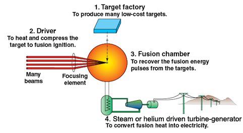 |
An inertial fusion energy (IFE) power plant consists of a target production facility (or target factory), target injection and tracking systems, the laser, a fusion chamber, and a power conversion system.
In the plant, many pulses of fusion energy per second (typically 10 to 20) would heat a low-activation coolant, such as lithium-bearing liquid metals or molten salts, surrounding the fusion targets. The coolant in turn would transfer the fusion heat to a turbine and generator to produce electricity. A NIF-scale laser operating at this repetition rate would produce more than 1,000 megawatts (MW) of electricity for the grid—enough to power a city the size of San Francisco.
The NIF laser operates at only a low repetition rate (a few shots per day), due to the need to carefully configure the research experiments and allow the facility's optical components to cool down between shots. The requirement to operate an IFE power plant at high pulse repetition rates requires the adoption of a new set of technologies:
Experiments on NIF will demonstrate ignition and energy gain—producing more energy from fusion than the laser delivers to start the process. For IFE, a gain between 50 and 100 is needed in order to minimize the portion of generated electric power that has to be recirculated within the plant to operate the laser.
The target factory must produce a continuous supply of high-quality targets at an acceptable cost—typically about one million targets per day at about 25 cents per target. The cost of the materials in the target is only a few cents; the majority of the cost arises from the production equipment and labor, as with most other mass-manufactured products. Detailed conceptual design studies for IFE target factories have been completed by LLNL and General Atomics, a participant in the National Ignition Campaign.
 |
Many types of targets are being considered for laser IFE, including indirect-drive (like those that will be shot on NIF), direct-drive (currently being tested on the OMEGA laser at the University of Rochester), and advanced designs including fast ignition and shock ignition (see Target Fabrication).
In all cases, the deuterium–tritium (DT) fusion fuel is contained in a spherical fuel capsule, held at low temperature so that it forms a layer of DT ice on the capsule's inner surface. The capsules are made of carbon, beryllium, or carbon–hydrogen polymers. NIF will be able to test full-scale targets for an IFE plant, using the as-manufactured products, and so directly underwrite the fusion scheme being adopted.
In direct-drive, the capsule is directly irradiated by the laser beams. In indirect-drive, the capsule is placed inside a hohlraum—a centimeter-scale, can-shaped container made with high-atomic-mass materials such as gold and lead with holes in the ends for beam entry.
 |
In NIF, targets are held in place at the center of the chamber A prototype gas gun target injection and tracking experiment at General Atomics showed that the accuracy needed for indirect drive targets can be achieved.and the beams are aligned to a fixed position for each shot. For IFE, targets will be injected at speeds greater than 100 meters a second and tracked in flight to provide data to a real-time beam-pointing system needed to assure the precise illumination required to achieve ignition and high energy gain. Target injection experiments using gas guns have been conducted at General Atomics, and tracking and engagement studies are under way. The required accuracy appears consistent with the use of existing technology and acousto-optic deflection technology to steer the laser beams onto the target.
While the total energy of the laser will be comparable to, or even less than, that of NIF, the IFE laser must operate at 10 to 20 shots a second, depending on the target yield per shot and the desired electricity output of the power plant. The vast majority of research on high-repetition-rate lasers for high-energy applications is focused on diode-pumped solid-state Lasers (DPSSLs), building on more than 35 years of experience with solid-state lasers leading up to NIF.
In addition to the ability to operate at high repetition rates, key considerations for the IFE laser include high efficiency (greater than 10 percent), low cost (to keep the price of electricity competitive with other energy options), long-life optics, high reliability, and low maintenance costs.
The Mercury laser projectat LLNL has been used to develop laser technology to meet these requirements, along with operational experience from the Laboratory's Atomic Vapor Laser Isotope Separation (AVLIS) facility and a range of other bench-top test facilities. AVLIS demonstrated the ability to operate high-power lasers running continuously for extended durations (10 years) at high availability (99 percent). Lessons learned from Mercury, combined with new developments in laser architecture and continuing improvements in components such as diode arrays and materials science, have defined the path to the design and construction of a beamline capable of driving an IFE power plant.
Each fusion target releases a burst of fusion energy in the form of high-energy neutrons (about 70 percent of the energy), X-rays, and energetic ions.
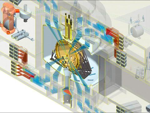 |
An artist's rendition of a LIFE power plant driven by diode-pumped solid-state lasers. Experiments at the National Ignition Facility will help provide the proof of concept for laser fusion power plants such as LIFE.The fusion chamber includes a meter-thick region that contains lithium (as a liquid metal, molten salt, or solid compound). This serves two purposes. First, it absorbs the fusion output energy, heating up to about 600 degrees Celsius. A heat exchanger is then used to drive a super-critical steam turbine cycle to produce the electricity. Second, this lithium "blanket" produces tritium through reactions with the fusion neutrons. This allows a closed fuel cycle to be formed, in which the power plant itself produces a key component of its own fuel. The other part of the fuel, deuterium, is extracted from seawater (roughly one part in 6,700). The deuterium found in just 45 liters of water, combined with the amount of lithium found in a single laptop battery would (allowing for inefficiencies) produce 200,000 kilowatt-hours—roughly 20 to 30 years' worth of electricity for someone living in Europe or the United States.
A key issue for the chamber is the survival of the innermost wall (first wall) that is exposed to intense heat and radiation from the target's X-rays, ions, and neutrons. Another key issue for the fusion chamber is intra-shot recovery: the conditions inside the chamber (such as vapor and droplet density) that must be recovered between each shot to the point that the next target can be injected and the laser beams can propagate through the chamber to the target.
Recent work at LLNL, in conjunction with partners across the United States, has produced an IFE power plant design known as LIFE (Laser Inertial Fusion Energy)to tackle these issues in a self-consistent manner using available materials and technologies.
By flowing a coolant through the fusion chamber at a steady rate, the pulsed fusion energy can be extracted at a constant rate and delivered to the power conversion system, which converts the thermal power to electric power. When liquids such as lithium metal or molten lithium salts are used for tritium breeding, the liquid is generally circulated as the primary coolant for the fusion chamber. When solid breeders such as lithium–aluminate (LiAlO2) are used, high-pressure helium serves as the chamber coolant. In either case, the primary coolant circulates through heat exchangers that power electric power equipment. The efficiency of the power conversion systems depends on the outlet temperature of the primary coolant, which is limited by the materials used in the construction of the chamber. Conversion efficiencies of 40 to 50 percent are now available for the temperatures produced from fusion, using technology developed for modern coal plants. Some work has also been done on concepts for converting a portion of the target energy output directly to electricity.
 |
An advantage of IFE is that the subsystems described above can be developed and tested separately, and often at lower cost than fully integrated facilities. The IFE power plant, however, requires successful integration of all the components with careful attention to the interfaces and the impact of design choices for one system on the others.
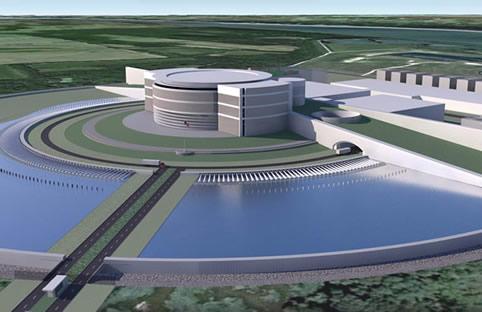
Artist's rendering of the exterior of a LIFE power plant.
Inherent safety and environmental sustainability are key benefits of fusion. Key characteristics include:
The consequences of accidents significantly beyond the design basis are well within regulatory limits, and represent a paradigm change from the dangers posed by nuclear power or gas transmission pipelines.